Monday 28 October 2019

Blackheath to the Beach

Blackheath to Manly, starting 6:05am, Sunday 27 October, 2019

The full ride. Grey Markers are rest/drink breaks except for
the 5th, which was to repair a wayward chain. 
On Saturday afternoon I took my pushbike and caught the 3:05pm limited stops from Central direct to Mount Victoria. It's a slow train, especially when it starts climbing it's way up the mountain. By the time I got to Mount Victoria and caught the all stops train back one station to Blackheath it was 5:30pm. I stayed at the High Mountains Motel, a comfortable budget motel about 100 metres on the west side of the highest point in the town. Once I'd checked in, it was down to the Ivanhoe Hotel for a T-Bone dinner. It's BIG!

I'd checked the temperature forecast before I left and the next morning was true to forecast, the outside temperature was a chilly 5 degrees Celsius. I left the hotel at 6:05am. I wore a thermal, a hi-vis long sleeve T-shirt and my riding shirt, with mittens under my riding gloves. That was about perfect for the upper mountains. By the time I got to Blaxland I shed the mittens and just went with the riding shirt. A bit brisk but better too cold than too hot. 

The ride down is excellent, with a generous and mostly cleared shoulder for almost the entire way, with only the stretch coming out of Blackheath and a stretch through Faulconbridge where the shoulder is rough and you are forced onto the road. At Blackheath the road is single lane each way, but by Katoomba it opens out to dual lane in both directions and most motorists give you plenty of room. The maximum speed limit is 80kph however that falls to 70kph and 60kph in parts. I rode on a Sunday morning and had no trouble on the mountain and enough room to enjoy the views and the air quality as I rode. The air through Faulconbridge is particularly floral. A big change from Sydney!

The are more uphill sections on the mountain than I was expecting but there's nothing too steep to slow you down too much. I took it easy because I knew there would be some hard yards at the bottom of the mountain but I'd love to go back and just ride down the mountain. That was by far the best part of the ride, with the exception of the arrival in Manly.

From Blaxland I took the turnoff at McDonalds and came down Mitchell's Pass. It's re-opened to traffic again but its still a far better option than coming down the freeway.

The track through St Mary's where the bike path runs out..

I stopped for a break after I'd crossed the Nepean (theres a new walkway bridge now), then headed through Henry Street in Penrith which is a ghost town on Sunday at 8am. There's a bike path from the top of Penrith to St Marys and though you have to cross the freeway a couple of times, traffic wasn't really that bad. At St Marys I turned off at Pages St, then left on Putland, Swanston, Morris to Marsden where I headed north and crossed the highway again.

...and through Mount Druitt to the M7. Not much traffic here.
That took me to Brisbane Street, then along Durham, left at Mount Druitt Road to Beames Avenue which takes you all the way to Rooty Hill Road, to Mavis and you are finally on the M7 Cycleway. The M7 Cycleway takes you all the way to the entrance of the M2. Crossing there there, I took the footpath on the eastern side of Old Windsor Road all the way to Parramatta. There are some funky turnoffs through that section so you really need to keep your eyes open for the signposts.


I rode through Parramatta Park and then across the river and followed the cycle track on the north side of the river. The cycle track is sometimes a little confusing so I had to stop multiple times to find my way but I think if you've done it once it would be easy. Just stay close to the river. You have to cross the river at one point to come back over the bridge to join the bike track again and that leads all the way to Ryde Bridge.

The section through Parramatta. Very fiddly, including the river cross just to cross back over on the bridge.

From there I had to head north to join the Epping Road cycle way and there's no easy way to get from Ryde Bridge to the cycle way so I just went up the footpath on Church Street, crossed Church Street at the top where it turns into Lane Cove Road and then crossed Victoria Road to Little Church then back to Church St, turned right down to Blaxland, turned right, then left on Princes to Buffalo, left and right to Gardener Avenue, right on Quarry, then left on Badajoz, then a quick right and a left to Blenheim and that takes you to the Epping Road Cycleway! I could have just stayed on Lane Cove Road all the way to the cycleway, but I was tiring by then and I don't like riding on main roads in Sydney in traffic. 

The Epping Road Cycleway took me all the way to Cammeray where I stopped for a sensational BLT at a small cafe just past the end of the golf course. That BLT, the coffee and the rest was the recharge I needed. I travelled through the Himalayas at the back of the west side of Mosman, over the spit bridge and victoriously up the aptly named Battle Boulevard. At the top of the Boulevard there's a stunning view all the way out through the heads along the east side of Edgecliff Esplanade. 

From there I could almost smell the beach. Straight down Sydney Road and onto Manly. Luckily I had my boardies with me and enjoyed a well earned swim. The water was FREEZING!

Stoked!

Statistics

Rider's age: Over 50
Total Kilometres: 143.5
Fastest Kilometre: 52.45 kph at Kilometre 20 between Wentworth Falls and Bullaburra.
Total Ride Time: 6:36:18, including stops for directions/drinks.
Total Elapsed Time: 8:14.
Average Speed: 21.74 kph. 

I don't like riding on roads where the speed limit is above 80kph
I don't like traffic lights, I'll go out of my way to avoid them.
I prefer quiet streets to traffic.
But that's just me...

Tuesday 26 February 2019

Electric Bike 2 - White Lightning : HASA/Bafang

Fresh from the experience with the construction of Electric Bike 1, I set out to correct the major issues with the first build, namely lack of power and range. It's almost impossible to understand what you'll get in terms of output just from reading specs, so the first bike was necessary to define the reality of a 250W 8.8amp/hour e-bike.

This time I didn't want to mess around. I looked at two, more powerful options, the Lunacycle 3000W mid mount (they are now selling a 7500W Monster!) and the Bafang HD 1000W Mid mount. In the end I went with the Bafang for the ease of install, the integrated controller and the apparently quieter operation. Plus 3000W? That's a beast!

I went native and found the best deal I could on China Vegas (Aliexpress.com) and after diligently checking all customer ratings and reviews, rolled the dice on a Bafang HD motor, replacement 42 tooth chain ring and a 52V 17.5 amp/hour battery. That set me back around $1,800AUD. Ouch. The Australian Peso strikes again!


The Bafang comes really well packaged with everything you need inside. I went with the optional top of the range display. All leads and connectors included and compatible.

The battery is gigantic. And Heavy.


Make sure you get the right size bottom bracket, there are three sizes, 68mm is standard but measure first!

I then needed a bike to put it on so I looked around for the cheapest mountain bike I could find with the specs I wanted:
  1. Disc brakes for better stopping power,
  2. 8 speed gearing because 8 speed chains are thicker and more robust than 9 or 10 speed chains. I was worried about the torque on the motor...
  3. Lightweight, aluminium frame (cos the battery already weighed a ton).
  4. A decent rear derailleur.
  5. Preferably 29" wheels.
  6. Cheap! (cos I'd already blown the budget on the motor & battery)
I didn't really care about the cranks or the front derailleur as I knew they would be removed anyway.

I found what I wanted in the HASA Galant 1.0 at CyclingDeal.com.au. Apparently reduced from $600.00 the bike only cost me $349.00 plus postage. Lightweight mountain bike, hydraulic disc brakes, 8 speed, Shimano derailleur, and 27.5" wheels (close) and super cheap!

The HASA comes partially assembled, putting it together was very easy and with the exception of a factory fault in the cassette, was complete in no time. I have to say the customer service from Cycling Deal in rectifying the fault was fantastic and with the replacement cassette in place, the bike was soon on it's way around the neighbourhood.


HASA Galant 1.0 straight out of the box.
The wheels looked really good for the price but that seat's gonna hurt... Right hand picture shows what came out of the box. Wheels, handlebars, pedals and seat is about all you have to do, the rest is just adjustment.


I set the bike up correctly for pedal power first because if I had any issues with the motor I wanted to know they weren't related to the operation of the bike.


Once the bike was setup, including gear settings, brakes etc., I grabbed the motor and began the install for that. The motor comes with zero instructions, but is relatively straight forward to install.

I removed the cranks and bottom bracket, then the motor just inserts directly into the bottom bracket socket.

There is geometry in all of this and once I'd installed the motor, I discovered the the crank casing was fouling against the frame.

I had to add a spacer between the motor and the bottom bracket to push the crank away from the frame. That impacts the geometry of the drive train, more on that later, but it allowed for a proper seating between the motor and the bike.

The final gap between the frame and the crank casing. I had to use about a 2.5 mm spacer.


With the motor through the bottom bracket and clear of the frame, it was then down to positioning.

In most installs I've seen on the web, the motor swings upwards towards the front of the bike, and is attached to the part of the frame that angles upwards towards the forks. However, the HASA has a flattened section on the bottom bracket with a considerable weld that that prevented that.

The motor sat snugly against this part of the frame and miraculously didn't foul the cable that ran below the bottom bracket and back to the rear derailleur.

It was almost like it was meant to be that way, and I couldn't think of a reason why the motor had to be attached to the front down tube. With the motor securely in place, I felt like I had just experienced one of those rare moments when things just fit together against seemingly impossible odds. A true workshop miracle. I thanked the saints and moved on.


The next part was easy, there is triangular shaped bracket that goes on the non chainwheel side, with the ridges on the plate facing into the bike, hard up against the bottom bracket. Two bolts hold it in place, tighten loosely until you have the bracket nut in place. The bracket nut is the solid nut, it goes flat face side into the bike. Tighten that to the suggested torque if you have the special tool to do that, otherwise use a hammer and cold chisel and give it some curry, like I did. Then tighten the two bolts on the triangular bracket. I put some lock-tite on the bracket nut, everything else comes pre coated.

Finally, tighten the outer facia nut onto the bottom bracket with a standard bottom bracket wrench.

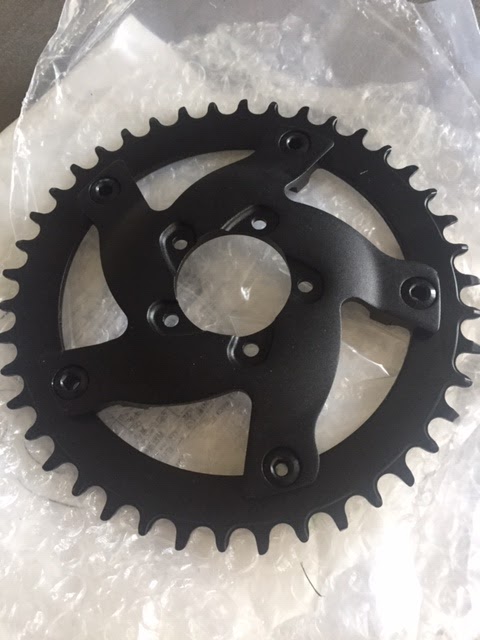
At that point the motor was in place and looking good. The motor comes with a 46 tooth chain ring that has a fairly deep dish to it which allows it to sit close to the bike frame. I'd purchased a 42 tooth chain ring to make pedalling easier if I ever ran out of juice.

While being a sanctioned replacement part, I don't think the 42 tooth has as deep a dish as the original, this means the chain ring aligns to a higher gear (smaller cog) at the back. This may have implications for additional load on the motor, which is then probably negated by the smaller chain ring.

I attached the replacement chain ring to the motor, I may experiment with the other chain ring later.


The replacement chain ring. Though it looks way better than the stock chainring it may not actually be a better choice.


Once that was done it was down to the crank arms. The motor comes with two crank arms that are seemingly identical, however as all great bike mechanics know, the thread on the left crank is reversed. So they're not identical.

Due to the excitement of getting the motor fixed onto the bike with almost no drama, I didn't even think of that until the exact moment when I had installed both cranks.

As expected, in a 50:50 bet, Murphy always wins so I switched the cranks over.


Booyah! This thing is starting to look real!


I attached the chain, given the chain ring was around the size of the middle crank that came with the bike, I left the length alone.

The battery installed easily, the bracket bolting into the drink holder sockets with plenty of room to spare although I did have to install the battery conceptually upside down due to the location of the drink holder. No big deal, the wires were long enough. The battery will need a strong zip tie due to the size and weight of it and the bolts are located towards the lower end of the bracket.

The electrics were next and the little gap in front of the rear wheel became a perfect place to feed the wiring. All the wires have colour coded plugs and arrows to line up the sides so it's almost impossible to go wrong. There's a wire that attaches the throttle to the monitor, which then has to connect to the motor, there are wires to hook up to the battery. Those were straight forward.

The brake levers that came with the motor are designed for calliper brakes and I though it's probably possible, I didn't want to remove the disc brake levers and replace them. This means there is no feedback to the motor when the brakes have been engaged. This is a sensible safety feature however if you back pedal just slightly the motor cuts out anyway so it's not really a big deal yet. I'll probably revisit the brakes down the track.

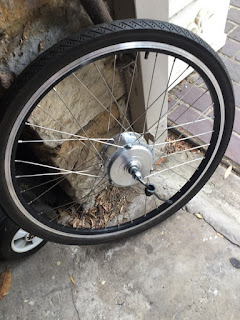
The last wire connects the motor to the speed monitor which measures the speed by the rotation speed of the rear wheel. The monitor sits against the frame next to the back wheel and a magnet attaches to the rear wheel. It's critical that these two items are lined up perfectly and as close to each other as possible. The positioning on the HASA was tricky because there's a brake cable in the way and the bracket seems to be a little to large but a couple of zip ties set it in place. If the positioning isn't in line or close enough the motor can't gauge the speed and will cut out. Another good safety feature.


The alignment and setup of the sensor and the spoke magnet. It's typically an easy install, better if your zip ties aren't bright yellow, but the bend in the Galant's frame didn't help, neither did the brake cable. That obviously wouldn't be there on a calliper system.


Mission Control. It looks like the monitor is covered in plastic but that's actually just reflection. To the left of the monitor is the on/off, assist and information selector, you can dial that in whilst in motion and to the left of that, the thumb throttle. Not exactly a black leather and chrome Harley look alike... Now there's an idea!


Time for a test ride! Yep, that seat's gonna hurt...


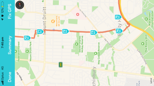
The first ride was short, to about the end of the street where the motor cut out. The display showed error code 21, which after some internet searching turned out to be caused by misalignment of the speed sensor. Once that was fixed I took the bike out for a quick 7km ride.

The bike has 9 assist levels, where 9 is the most powerful. 9 takes a while to get used to as the bike just takes off. 4 is a good place to start. The assistance feature is great and you can use the throttle while the assist is on.

The throttle (and the assist) isn't really a throttle as such, on the setup I have it's almost like an on/off switch for power. Power is delivered gradually, to a maximum, almost like the motor winding up.

The chain needs to stretch laterally. The chain ring doesn't seem to like moving through too many gears and now that the bike is effectively a 1-8 configuration there will need to be a little more give in the chain to keep it on the cogs. I expect that will occur through use.

After 7km the bike was barely showing any power loss in the battery. This is obviously overstated so will need to be watched. It's likely that the battery monitor may appear to discharge faster as the power is used up.  I think the speedo is also overstated. The bike was showing a top speed of 57km/hr down a considerable hill. While that's not out of the question, I didn't feel like I was going that fast. More accurate measurement is required.

Other than that the bike is incredible. It flies up hills and the assist is super relaxing. You don't really need to use the motor on the flat but I found I couldn't resist, you can just fly along at speed and the front cranks stay stationary as the motor turns the chain. It's absolutely brilliant.

Stoked!

Friday 22 December 2017

Electric Bike

The Build

The goal of the Electric Bike Project was to provide a relatively inexpensive way to get to the ferry from where I live so I can get to the city for work. I live in a fairly hilly area and the idea was that the electric motor would handle the uphills (so I wouldn't be sweaty mess by the time I got to work) and I would handle the downhills. :)

The specification of the kit:
Model (year)RAKLO A-Kit (2016) FWD
DesignationStreet Legal
Main UseRecreation, commuting
Nominal Power250W
Cruise Speed25km/h
Max Speed25km/h assisted, further speed can be achieved from pedalling
Max Range50km
Average Range30km
Throttle TypeTwist Throttle with grips
Pedal Assist Levels3
Handlebar DisplayLED 880
Weight10kg total
Battery36V 8.8Ah Rack

The target bike, generously donated by Brendon, the mighty Norco Kokanee. The bike is a relatively inexpensive entry level mountain bike, with a few miles on the clock. In perfect working order, (give or take), the current gearing is 3x9, the front chainwheels are tiny.
…and the AKLO conversion kit. The kit is a rack style kit which suited me as I take a bag to work. You can see the wheel (no tyre or tube but does have rim tape), the rack which houses the battery and two boxes. The boxes contain the controller, the wires, some keys to lock the removable battery in the rack, the monitor, the charger and a bunch of other bits and pieces.

The only thing missing was the instructions... I couldn't find them anywhere on the net so I just got on with it.

Step 1: Put a tyre and tube on the rim.
Nothing too difficult there..


Step 2: Attach the wheel to the forks.
The axle was too large for the forks so I
had to file the drop outs back a fraction...

Step 3: The axle washers were also too
large so they had to be ground back too...

The wheel locked into the forks. For the professionals among you, you may notice the wheel is the wrong way around, creating a bike that only goes in reverse. What can I say, I had no instructions and on a 50:50, Murphy always wins.

I fixed that later.
Step 4: Put the rack together. This involved adding the extension legs to the rack frame to attach the rack to the bike just above the rear axle and to position the lugs that hold the rails that attach the rack to the seat post.

The lugs didn't sit flush in the channel which
meant the attachment bolt was too short.
So I ground the edges off the lugs.
Problem solved
This picture shows the lugs holding the bolt that holds the seat post rails. Seems unnecessarily complicated...
And finally the attachment to the seat post. I removed the seat post quick release and just used a standard bolt because with the addition of the rack rails the quick release was no longer long enough. The bolt is better security anyway.
Booyah, the rack is on.
Step 5: Attach the controller. The kit comes with a particularly flimsy bracket to hold the controller to the frame and the controller only has one tab for the attachment to the bracket. The bracket was supposed to attach to the down tube but I couldn't see a sturdy way to achieve that, particularly with everything else that is already crowding out the down tube.
So I created a small carriage that sits under the battery to hold the controller. Very sturdy, but I'm not sure how hot the controller gets under use. I may have to revisit this once the bike has been tested on the road.
Suddenly a huge wasp flew into the workshop. Probably to get out of the thunderstorm which brought hail. Work had to stop for a short time while the car was moved into the garage... Sadly, the wasp overstayed his welcome.
Another view of the rack and controller.

Step 6: Attach the cadence disc for the
electronic assist. That was no trouble....


...but the sensor wouldn't fit due to the
low lying derailleur. So I just left that
off. May revisit that with another chainwheel/derailleur, but that hardly
makes sense on this bike.
Step 7: Connect all the wiring. This was straightforward, all the wiring is colour coded and marked with arrows.

Step 8: Tidy up the cables..


... and the job is done. You can see the throttle attached on the right...
These are the leftovers. From left, the cadence disc sensor, the controller bracket(?), the handgrips, these didn't fit the handlebars, even though the handlebars are a standard small diameter. Note that the throttle wouldn't fit on large diameter handlebars. Finally, the brake sensors wires. These aren't really required if the cadence sensor is not on.

Assessment

The kit is relatively easy to install, although there are a number of minor issues that required adjustment, at least on the bike I used.

I'm a reasonably big bloke, (6'3" 85kg) but I have to say I was disappointed with the hill climbing power of the kit. On a fairly modest incline the bike struggled on it's own but when assisted with some pedal power, was more than happy to climb the hill. Under pedal power, it was noticeably easier to climb the hill with the throttle also on full. I expect the kit would need to be more powerful to achieve the hill climbing power I was hoping for, however that would probably cause the speed on the flat to significantly exceed the 25km/hr speed limit for bikes with these kits. That speed limit doesn't make much sense, 25km/hr is a reasonable, average speed for an unassisted, good rider, including uphills and downhills so the average human powered downhill speed would easily exceed the theoretical speed limit of an electric bike anyway.

I think I may have been overly optimistic regarding the power of these kits. They are fine under assistance but struggle on their own on fairly modest hills. It's great to move along without having to pedal, but ultimately, the kit didn't satisfy my requirement. I gotta get a bigger motor...

Friday 1 December 2017

Ultimate Guitar Project: Little Wing

The Design Goal 

The idea behind Little Wing was to design a unique looking guitar that still kept the playing feel of a Strat. The success of the Statocaster is a testament to the brilliance of Leo Fender and I wanted to maintain some of the key features of the Strat, but I didn't want to build "just another Strat copy."

There had to be a contoured face for the forearm, a cutaway for the ribs an when the guitar was played sitting down, the knee rest should put the strings and bridge in roughly the same place as they would be if you were playing a Strat.

The pickup configuration for me has always been based on a 3 pickup Strat and my goto pickup is the middle pickup. I find the bridge pickup too thin so I've switched that out for a humbucker as I never use the single coil bridge pickup. I rarely use the neck pickup other than for noodling so a single coil works best for me there too.

Minimal controls, minimal fuss.

Creating the Body Template

I drew the body template into a sketch pad and continued to make adjustments until the shape looked about right. Then I photocopied and enlarged the design across two A3 sheets until the size was right. At that point the rough outlines could be smoothed to form the final shape. 
I traced the shape onto 9mm MDF and cut that out with a jigsaw using a rasp and file to smooth the outline of the template. 9mm provides a sufficient guide when using the router.  Finally I sanded the edges  to ensure that the curves were smooth to the feel.

The finished template for "Little Wing"

Cutting Out the Body.

The body wood was salvaged from and old table, slightly concave on one side, and slightly convex on the other. The wood was partially covered in silver paint, and there are visible surface cracks in the wood which hopefully will sand out once the body shape nears completion.
The underside of the table top. The two gouges are where the legs were once attached. The underside was bowed but the template had to be placed on this side so that the template missed the gouges. I wanted the underside of the table to be the back of the body, making sure the grain travelled lengthways along the body.

I traced around the template and used a hand-held jigsaw to cut the shape out. That took some time with a coarse, fast cutting blade because its a bloody thick piece of wood. The first picture shows the back, the second shows the front. Not exactly a work of art yet... You can see some surface cracks but luckily, I missed most of them.


Routing the Body

First I drilled a couple of pilot holes through the templates and into the body, one at the point where the middle bridge screw will be and a couple in the rough beyond where the neck will finish. These holes allow a centre line to be redrawn if the centre line gets sanded off. This turned out to be a great idea. The surface of the top was very rough...with significant cracks.


Neither side of the body was actually flat, the top being bowed slightly and the underside lumpy. I started with the underside. My first attempt to smooth the base with a power planer that was a little past its prime, was a disaster. Deep, rutted grooves appeared where the blade dug in over the rough surface.


So I rigged up a makeshift "thicknesser" by nailing two boards that I knew were flat onto two blocks that I knew where the same height. A sheet of 9 mm MDF held it all together. The body was attached to a base board by a screw through the neck excess and double sided tape at the other end. The base board then slid between the supports, moving the body underneath the routing window of the guide boards. Using a wide, flat bit, all I had to do was move the router back and forth over the guide boards as the bit cut into the surface of the body. The gap between the guides was about 100 mm, the bit was about 22mm wide so I got about 4 passes before I had to move the base. Once I'd done the underside, I flipped the body over and did the top.


Awesome! Perfectly flat! That worked even better than I thought it would! All up I took a little over 7 mm off the thickness to bring it back in line with the body thickness of a Strat.


Cracks are still visible but not a big deal. In fact I kind of like the look.

Next step was to route for the neck and pickups. Using a template that I made earlier, I aligned the template with the pilot holes attached the template to the body. The depth of the pickup routes was deeper than the neck and not super critical as long as there was enough space for the pickup. The depth of the neck was critical. The first route used the template as a guide, the rest was done using the cavity as a guide to route out to depth. The blade on the router bit was only about 20mm deep. The end result was starting to actually look like a guitar.


The next step was to route around the shape itself. This took three goes to get the full depth done, two steps with the bit with the bearing on top, first tracing around the template, then tracing around the body itself. Finally, one pass with a bit with the bearing on the bottom from the underside. Good quality bits make a HUGE difference, the cheaper bits tending to rip rather than cut.


The edges needed a final sand but a lot of the difficult routing bits are done. From here I had to finish the neck pocket, round the edges and route the control recess.

The neck pocket was the site of multiple near disasters. The depth of the pickup routes was 37mm. The neck pocket depth was the depth of the neck I had, below the fingerboard. The neck I'm using has a shallower heel than a standard Strat. Fortunately I realised that prior to the cut...


While routing the body edges, the bit nearly chewed into the neck pocket had I not realised at the last moment. Routing is a VERY easy thing to mess up. As you move past the body there is nothing for the bearing to run against and the bit will cut straight into the neck pocket. That was a close shave.

Routing tips.
  • Don't try and route the whole thing in one go. Cutting a medium amount of wood out multiple times is far better than plunging in and trying to route the whole thing at once. I drilled out as much wood as I could with a Forstner bit prior to routing, to save the router bit.
  • Hold on tight, the router can kick.
  • When you want to stop, move the bit off the edge of the job and release the trigger. Let the bit stop before trying to lift the router from the job otherwise you'll gouge out chunks for sure as you try to lift the still spinning bit off the job.
  • Find the way the router wants to go relative to the grain and go that way. Don't fight the router.
  • Always unplug the router before changing bits!
  • My router is a plunge router and you have to be The Mighty Thor to be able to control the plunge because the springs are quite stiff. So I lock the router in the down position and slowly lower the bit into the work by keeping one edge of the router base on the job and lower the bit in that way. That's one less thing to think about while routing. Otherwise, if the router slips up on the springs you stand an excellent change of gouging a huge chunk out of the job and template. I learned that the hard way.
  • Use the best quality, sharpest router bits you can find.  

The Neck Pocket


\  
So the question was, how was I going to clean up the mess around the neck pocket? The router couldn't run around the body anymore as I'd already routed out the pocket. I thought of routing from below but I still had no guide, or attaching the actual neck and routing that from below with the bit with the bearing on the bottom, but nothing seemed too promising. I eventually decided to make a fake neck stub and route around that. As unlikely as it may seem, that worked out well...

The picture shows how close I came to gouging into the neck pocket. The wood in one section is almost see through.

To make the neck stub I took a piece of scrap pine and traced the neck route onto it. I cut around that with a jigsaw and then sanded the shape back to a tight fit. I ran the stub against another block of scrap to keep the sides flat. The stub didn't have to fit perfectly but it did have to have straight sides. (Note: I could have done this the same way I did Sheena's shim...)

 
Once I was happy with the stub, I ran the router bearing along the edge of the stub to cut away the excess below. The excess at the end of the neck pocket was just enough to support the router so I could complete the side routes. Then I measured the length of the neck pocket and cut the end off with a jigsaw running along a fence for a straight cut. The neck fit in beautifully with maybe half a mil gap between the underside of the fretboard and the surface of the body. Booyah!

The Control Cavity

The next route was the control cavity. I didn't want to use a pickguard so I had to route a hole out of the back. I started by cutting out a section of the body template that would house the controls. Then I clamped the template to the body and used a Forstner bit to remove as much wood as I could then routed out the rest.
 
The control cavity had to be to a depth within about 7mm of the front surface as that's about the length of the shaft on a standard pot and switch. That section of the work was measured 10 times and cut once. The photo to the left is pre-route/post-Forstner.
 
BTW, you can see I'm still using the "thicknesser". It's been super useful and has become my new work bench. You can clamp all over it, it's stable and it's flat. Best thing I've ever made.
To cover the control cavity I wanted to create a custom control plate cover and recess that into the back (because there are far more ways to completely destroy the body that way...) so I drew a shape that would cover the control cavity with about a 5mm gap around all the edges. I cut that shape out of some 9mm scrap MDF and smoothed it with sandpaper. The corners were rough but the router bit's bearing would define those anyway.

The creation of the template was a bit awkward as the controls are located on the top and you obviously have to route from the bottom. Maybe I should have drilled the control holes from the top all the way through and then designed the control route around that. Once I'd routed the cavity I drilled pilot holes from the bottom through the top and then drilled the final holes from the top through to the bottom.

I sat the control cover template on two pieces of wood so that I could run the router around the edge of the template while the bit barely touched the surface of the body. The bearing is at the top of the bit and the bit is about 20mm deep. I only need to route out a depth of about 2mm so I dropped the bearing about 2mm into the template. The picture on the left shows the routing sandwich. Template on top, nailed into two spacer blocks, clamped to the body. The picture on the right shows the view from above, through the template, post-route.

The finished control cavity. Very happy.


The Control Cavity Cover

The next challenge was to create a control cover that fit exactly into the shape I'd just carved into the back of the body. I'd bought a back plate for a Strat tremolo so I used that as the stock. Probably an expensive way to do it...

I gaffed the plate to the control cover routing template, making sure it couldn't move. Unfortunately, I gaffed the back plate the wrong way around (twice...) and damaged the protective plastic cover on the plate.
Having finally correctly gaffed the plate, I scored the plate with an Exacto knife by following the edges of the template. I ran around the template a number of times CAREFULLY so there could be no doubt where the line was. I didn't worry too much about the corners.

I used a jigsaw to cut around the outline then used a Dremel on a slow speed with a sanding bit to sand the plate back to the scored outline. When I was close, I hand sanded the plate edges smooth and slowly and patiently, made slight adjustments until the plate fit into the cavity.
The completed control route and cover. A couple of drill holes and it's done. Stoked with that outcome.
 
“Patience and perseverance have a magical effect before which difficulties disappear and obstacles vanish.”
John Quincy Adams

Rounding the Edges

After all that, this was a relatively simple step and therefore the one most likely to cause irreparable damage. Using a curved router bit I ran the router around the edge of the body, top and bottom. There are so many curves and corners on this thing that considerable patience and concentration were required to complete the job. After a quick sand the routing of the body was finished. Or so I thought...

Carving Out the Contours

To shape in the contours I took to the body with a sanding flap disk on the angle grinder. Quite brutal but very effective in removing wood quickly especially considering this was not a soft piece of wood!

I had to be careful in the tighter curves and try and maintain a smooth transition with respect to all surfaces. The flap sander was surprisingly effective and MUCH faster than the alternative (the rasp, I don't have a spokeshave). Slow and steady was the name of the game as you can't put the wood back!

Once I'd completed that task, the body was starting to look like a real guitar.
It's essential that the edge rounding is done on the front and back sides of the guitar before the contour step as the edge rounding provides a consistent rounded edge around the body and even though you will destroy that consistent edge in the places where the angle grinder goes to work, you still have a guide for what the edges should look like. It would be almost impossible to apply the edge rounding after the contours were cut out because the substrate for sections where the router would travel would have been removed.

The contours were based loosely on the contours of a standard Strat although given the variation in the shape, feel slightly different. Much better than just rounded edges though.

The Beauty in the Beast

It looks like I cut it pretty fine on the back leg slot on the table top but I actually gave myself plenty of room for the jigsaw. Given how hard the wood was, the jigsaw blade had a tendency to angle back into the work as the blade travelled around the curves in the template.

Mounting the neck

The next step was drilling out the holes for the neck screw buttons. The buttons are flat on the bottom so the critical measurements were the circumference size, (there appears to be no standard between suppliers) and the depth to drill the hole. I must have drilled a dozen holes in scrap to get the hole just right.

I don't have a real drill press so I just used the portable drill stand that I had. The amount of movement in the drill stand in the picture is huge so I had to be extremely careful, however the stand did provide a stop to the depth of the hole. A sharp spade bit did the job.

I knew I wanted to round the heel, so I offset one of the holes to allow for the rounding.

Then using a rasp, I shaped the heel and finished it up with sandpaper. There was very little space for the drill stand and considering the movement in the stand, the result turned out pretty well.


Attaching the Neck

From there I lined up the neck in the neck pocket and clamped it to the body. I already had a guide for the drill holes from the spade bit's centre spike so using extreme care with the depth, I hand drilled the holes through the body and into the neck. Then with great anticipation, screwed the neck onto the body.

Very happy with the attachment of the neck and the depth of the neck pocket route. Add some paint and that's pretty much perfect! Except...
As it turns out, once I'd assembled everything, I discovered that the part of the neck that overhangs the body should allow for the thickness of a pickguard (whether you use one or not). Once I'd put the bridge on and strung the guitar, there wasn't enough adjustment on the bridge to allow for the action I wanted. So I had to decide to shim the neck with a 2-3mm thick piece of something and have the overhang sit above the surface of the body, or sink the bridge into the body. I chose to sink the bridge and out came the router again...

The bridge mounted and strung with the saddles set to minimum.

The action was way too high. You could limbo under that!

Drilling out the body

After the neck was attached and the guitar was playable, it was time to drill out the body. That includes the holes to screw on all the hardware and the hole for the wiring. On guitars with pick guards this is not an issue as a channel is typically routed between the pickups. For this guitar a hole had to be drilled for the wiring. I found a cheap drill on AliExpress (actually bought two, the first had a hard time going through melted butter) but this one was excellent. And long. Really long. Rather than try and angle the hole I decided to just drill straight through from the neck pocket, even though the neck side hole was not required.
All the body hardware attached and the bridge sunk into the body...
...and naturally, the control route was just a fraction too shallow...

Sou out came the router again.....

Though the drill out and pre-paint assembly is tedious, it's absolutely essential, due to little issues like this.

The cracks in the body are obvious and I REALLY like them. 
In order to preserve the cracks so that they looked authentic when I applied the wood dye, I tried to fill them in with something clear to maintain the look of the crack. I didn't really want to use wood filler because that always looks naff. I tried clear Araldite, wood glue and finally settled on many, many coats of clear nail polish.
In the end I got it sanded back but it was a challenge. As the nail polish was sanded it would start to expand and go gummy. Frustrating.

Finishing

In my head I had a picture of a dyed purple guitar with the grain of the wood shining through, but after the first coat of the wood dye I was wishing I had just left it as a plain wood finish. Though it's not that noticeable from the photo, there was a section of the wood that loved the dye and went bright purple. The rest of the body turned a pretty mundane purple-ish wood colour.

That was nothing like the picture I had in my head...
In the end it may have come out alright for most of the body but I didn't want the bright purple shiny patch messing with the finish. So I decided to paint.
I struggled with the paint. I originally though that the more coats the better but after a while the surface degrades with the thickness and you start to lose the gloss.

Paint is not easy. You need to sand the wood back to glass smoothness. Paint a generous coat of primer/sealer, then sand that back to glass smooth. Then it should just be two coats of colour and two coats of clear. More coats is NOT better. I also should have built a dedicated stand that allows you to paint with the spray can upright for the face and back of the body. Instead, I painted with the body flat and angled the can. Not ideal.
More paint tips:
  • Follow the instructions on the can re distance to hold the can from the job. Different paints dry more quickly through the air and you don't want dry paint hitting the job.
  • Do the second coats as soon as possible after the first so that they meld together.
  • Wait between the colour and the clear coats.
  • Auto paint is excellent for the colour coats particularly the pearl or mica finishes. I just used the touch up spray cans for colour and a spray on 2-pak clear for the clear coats. Standard acrylic does not dry as glossy.

Once the paint dried, it was just a matter of re-attaching the hardware and the neck and getting the guitar ready for final setup.

Gallery